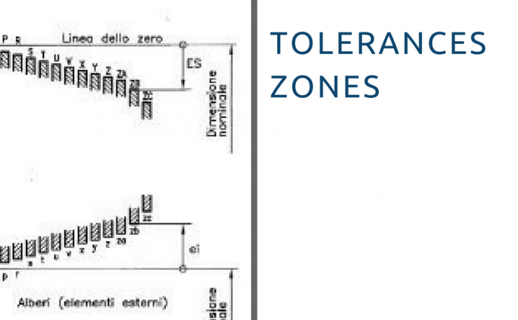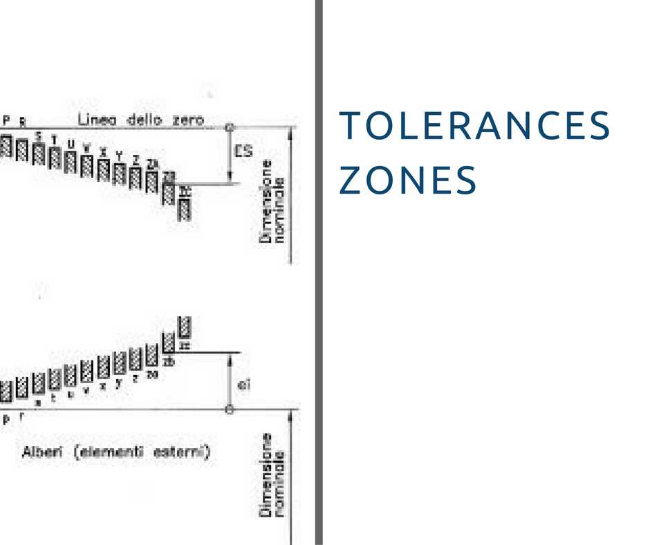
Position of the Tolerance Zone
Today we are going to address the theme “tolerance“. In particular we would like to give some clarifications on tolerance zones.
The width of the tolerance zone
In the ISO system, the width of the tolerance field is determined by the degree of tolerance normalized. (IT)
But how many are the standard tolerance grades? These are 20, named with abbreviations from IT0 to IT18, the width of the tolerance field is a function of two parameters:
- Nominal dimension
- IT’s value.
Based on their accuracy, you can find 3 groups of tolerances:
- Working gauges (shafts from IT01 to IT4, holes from IT01 to IT5)
- Working gauges (shafts from IT01 to IT4, holes from IT01 to IT5)
- Precise machining (shafts from IT5 to IT11, holes from IT6 to IT11)
- Rough machining (shafts and holes form IT12 to IT18)

The position of the tolerance zone.
The position of tolerance in relation to the zero line is designated by a letter indicating the reference offset value the reference deviation, depending on the case, may be:
- Superior (holes: for positions from “K” to “ZC”)
- Lower (holes: for positions from “A” to “H”)
- Line zero (holes: deviations “JS” and “js” tolerance zone over the zero line)
In the ISO system, there are 27 standard designated location:
- For holes with letter from “A” to “ZC”
- For shafts form “a” to “zc”
The deviations “H” and “h” define respectively:
- minimum dimension tolerance zone corresponds with the nominal size (holes)
- maximum dimension tolerance zone corresponds with the nominal size (trees)

Come to our web shop Inoxmare! Submit your orders and quotations with one click. Registered. Even from your mobile phone. Check out our discounts, availability and prices. Over 20,000 stainless steel items to choose from.
Click here


